Wheel loader connecting rod spare parts for XCMG Liugong wheel loader

Connecting rod
Because there are many kinds of spare parts, we can’t display them all on the website. Please feel free to contact us for specific ones.
Advantage
1. We supply both original and aftermarket products for you
2. From the manufacturer to the customer directly, saving your cost
3. Stable stock for normal parts
4. In Time Delivery Time, with competitive shipping cost
5. Professional and on time after service
Packing
Carton Boxes, or according to clients’ request.
description
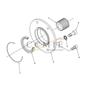
The function of the connecting rod is to connect the piston and the crankshaft, so that the reciprocating linear motion of the piston becomes the rotary motion of the crank to output power.
The connecting rod body is composed of three parts, the part connected with the piston pin is called the connecting rod small end; the part connected with the crankshaft is called the connecting rod big end, and the rod connecting the small end and the big end is called the connecting rod shaft. The small head of the connecting rod is mostly a thin-walled circular ring structure. In order to reduce the wear between the piston pin and the piston pin, a thin-walled bronze bushing is pressed into the small head hole. Drill or mill grooves on the small head and the bushing to make splashed oil enter the mating surface of the lubricating bushing and the piston pin. The connecting rod shaft is a long rod, and the force is also large in work. In order to prevent its bending and deformation, the shaft must have sufficient rigidity.
According to whether the relative movement between the components is a plane movement or a space movement, the linkage mechanism can be divided into a plane linkage mechanism and a spatial linkage mechanism. The plane linkage mechanism is a common transmission mechanism. It means that the rigid components are all connected with low pairs, so it is also called low pair mechanism. The plane linkage mechanism is widely used in various machines, instruments and control devices. Such as reciprocating engines, pumps and air compressors, as well as planers, slotting machines, excavators, loaders, jaw crushers, swing conveyors, printing machinery, textile machinery, etc., the main mechanisms are flat linkage mechanisms. In the linkage mechanism, if the components do not move in the same plane or parallel to each other, the mechanism is called a spatial mechanism. [3] According to the number of components in the mechanism, it is divided into four-bar mechanism, five-bar mechanism, six-bar mechanism, etc. Generally, five-bar and more than five-bar linkage mechanisms are called multi-bar mechanisms. When the degree of freedom of the link mechanism is 1, it is called a single degree of freedom link mechanism; when the degree of freedom is greater than 1, it is called a multiple degree of freedom link mechanism.
According to whether the kinematic chain forming the linkage mechanism is open chain or closed chain, the corresponding linkage mechanism can also be divided into open chain linkage mechanism (manipulator is usually a spatial open chain linkage mechanism in which the kinematic pair is a rotating pair or a moving pair) And closed-chain linkage mechanism. The number of components of a single closed-loop planar linkage mechanism is at least 4, so the simplest planar closed-chain linkage mechanism is a four-bar mechanism, and other multi-link closed-chain mechanisms are nothing more than the expansion of the rod group on its basis; single closed-loop The number of components of the spatial linkage mechanism is at least 3, so three components can form a spatial three-bar mechanism.
Link mechanism components have various forms of movement, such as rotation, swing, movement and complex movement in plane or space, which can be used to realize known motion laws and known trajectories.
Advantages
(1) Low pair: surface contact, large load bearing, easy to lubricate, not easy to wear, simple shape, easy processing, easy to obtain high manufacturing accuracy.
(2) Changing the relative length of the rod, the movement law of the follower is different.
(3) The contact between the two components is maintained by its own geometric closure, unlike cam mechanisms that sometimes need to use springs and other force closure to maintain contact.
(4) The connecting rod curve is rich, which can meet different requirements.
Disadvantages
(1) There are many components and motion pairs, large cumulative error, low motion accuracy, and low efficiency.
(2) Dynamic load (inertial force) is generated, and it is not easy to balance, and it is not suitable for high speed.
(3) The design is complex and it is difficult to achieve precise trajectories.
Therefore, the plane linkage mechanism is widely used in various machinery, instruments and electromechanical products. With the development of link mechanism design methods, the popular application of electronic computers and the development of related design software, the design speed and design accuracy of link mechanisms have been greatly improved, and while meeting the kinematics requirements, it can also be considered To the dynamics. In particular, the introduction of microelectronic technology and automatic control technology, and the adoption of multi-degree-of-freedom linkage mechanism greatly simplify the structure and design of linkage mechanism and have a wider range of applications.
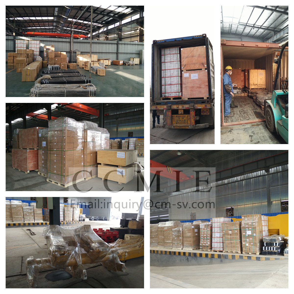
our warehouse

Pack and ship
- Aerial Boom Lift
- China Dump Truck
- Cold Recycler
- Cone Crusher Liner
- Container Side Lifter
- Dadi Bulldozer Part
- Forklift Sweeper Attachment
- Hbxg Bulldozer Parts
- Howo Engine Parts
- Hyundai Excavator Hydraulic Pump
- Komatsu Bulldozer Parts
- Komatsu Excavator Gear Shaft
- Komatsu Pc300-7 Excavator Hydraulic Pump
- Liugong Bulldozer Parts
- Sany Concrete Pump Spare Parts
- Sany Excavator Spare Parts
- Shacman Engine Parts
- Shantui Bulldozer Clutch Shaft
- Shantui Bulldozer Connecting Shaft Pin
- Shantui Bulldozer Control Flexible Shaft
- Shantui Bulldozer Flexible Shaft
- Shantui Bulldozer Lifting Cylinder Repair Kit
- Shantui Bulldozer Parts
- Shantui Bulldozer Reel Shaft
- Shantui Bulldozer Reverse Gear Shaft
- Shantui Bulldozer Spare Parts
- Shantui Bulldozer Winch Drive Shaft
- Shantui Dozer Bolt
- Shantui Dozer Front Idler
- Shantui Dozer Tilt Cylinder Repair Kit
- Shantui Sd16 Bevel Gear
- Shantui Sd16 Brake Lining
- Shantui Sd16 Door Assembly
- Shantui Sd16 O-Ring
- Shantui Sd16 Track Roller
- Shantui Sd22 Bearing Sleeve
- Shantui Sd22 Friction Disc
- Shantui Sd32 Track Roller
- Sinotruk Engine Parts
- Tow Truck
- Xcmg Bulldozer Parts
- Xcmg Bulldozer Spare Parts
- Xcmg Hydraulic Lock
- Xcmg Transmission
- Yuchai Engine Parts