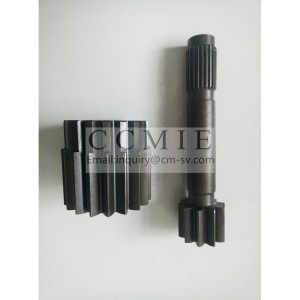
Driving cylindrical gear truck spare parts for XCMG HOWO truck
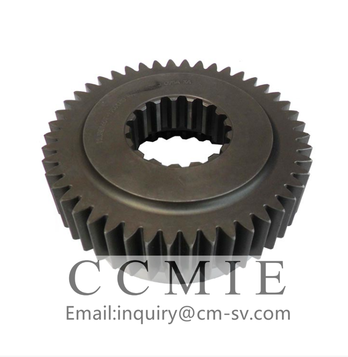


Driving cylindrical gear
Because there are many kinds of spare parts, we can’t display them all on the website. Please feel free to contact us for specific ones.
advantage
1. We supply both original and aftermarket products for you
2. From the manufacturer to the customer directly, saving your cost
3. Stable stock for normal parts
4. In Time Delivery Time, with competitive shipping cost
5. Professional and on time after service
packing
Carton Boxes, or according to clients’ request.
description
Because of the thick and thin wall characteristics of auxiliary box drive gear parts, the corresponding forging mold cavity is also relatively deep and the cavity wall is thinner. During the forming process, it is easy to cause cracks in the thin wall of the mold, resulting in poor mold life. High, the cost of forgings remains high.
original technology of auxiliary box drive gear
Figure 1 Drive gear of a certain auxiliary box
Under normal circumstances, open die forging is the most widely used die forging method for auxiliary box drive gear parts. The advantage of this method lies in the thickness of the die wall. The force of the mold acts as a buffer to ensure the life of the mold, but the material loss of the flash is 10%-50% of the weight of the forging, an average of about 30%, and the material cost accounts for 60%-70% of the cost of the die forging, so We changed this type of forgings to closed production.
Cause Analysis
Closed die forging is that the blank is deformed into a forging in a closed groove by upsetting or extrusion. Compared with open die forging, the final formed part of closed die forging must be filled with the blank by the die wall, which requires higher die wall strength. In the previous design, only the cavity of the forging was considered, and the strength of the die wall was not considered enough. However, the part shown in red in Figure 2 needs to be filled. After the blank contacts the outer wall, the die must continue to be pressed, resulting in excessive force on the die and the wall of the forging die. Weaknesses, especially the root fillet (Figure 3), break due to excessive force in the later stage of forming.
Improved closed hot die forging process
In order to improve the life of the mold, for such thin-walled flange forgings, we have unified consideration of changing the mold structure, changing the overall structure of the mold into a body structure, and adjusting the mold design ideas. In order to prevent excessive force on the mold at φ89.6mm, we made the difficult-to-fill φ66.5mm part into a separate structure, and at the same time increased vent holes at φ89.6mm to reduce the suffocation during the forming process, as shown in Figure 4. Shown. After the change, the mold life has improved significantly, from the previous 1500 pieces to about 3000 pieces, but it still cannot meet the needs of on-site production, especially the mold life needs of automatic line production.
We re-analyzed the entire forging, and under the premise of not changing the materials used in the forging process, we guarantee two points for the design of the pre-forging die and the final forging die: first, to ensure that the die life meets the design requirements without cracking; second, the forging The mold ejection is smooth, and there will be no jamming phenomenon. We believe that the thickness of the side wall of the upper die of the forging is small, and the impact force on the upper die is much greater than that of the lower die during the forming process of the forging. Therefore, the forging is designed to turn around, that is, the thick wall part of the die is designed on the upper die. The thin-walled part is designed in the lower mold, and the thin-walled part of the lower mold and the forming outer ring are designed as a whole, as shown in Figure 5 marked 43 mold outer ring. In the design process, the pre-forging design is the most critical and can best reflect the designer’s technical level. Pre-forging mainly plays a role of material separation, which can prepare for the final forging forming. In design, we ensure that the pre-forged part is as thick as possible and fills the cavity in the final forging groove, without blank reflow, so as to reduce the back-extrusion of the forging as much as possible, reducing the forming force and reducing the folding of the forging. The resulting risk.
After the die design is carried out according to the new idea, the forgings are full and the die life reaches the design requirements. When the mold is used on a multi-station or high-energy screw press, the life of the mold is increased by more than twice the original, thereby reducing the cost of forging and reducing the labor intensity of workers.
in conclusion
This article draws the following conclusions by comparing the different mold design processes of the auxiliary box driving gear parts:
When designing the pre-forging cavity, it is necessary to consider the material distribution and the flow mode of the blank during the forming process of the forging.
The closed process of this type of high-wing drive gear is different from the closed process of other gears, especially on high-speed automatic lines. Because the walking beam is relatively fast in transmission and cannot be interfered by manpower, it is necessary to fully consider each in the design process. The positioning of the working steps and the distribution of materials must be accurate, especially the design of the pre-forging cavity must be prepared for the final forging forming.
For most high-energy presses, there are usually only upsetting and final forging steps, and die design is more difficult. The preferred final forging cavity design can reduce the scrap rate of forgings, and at the same time avoid the shortcomings of thin and easy cracking of the die wall due to the product structure, thereby effectively reducing the cost of forging.
The mold design of the auxiliary box driving gear parts has reference and reference significance for the design of other molds with similar structures.
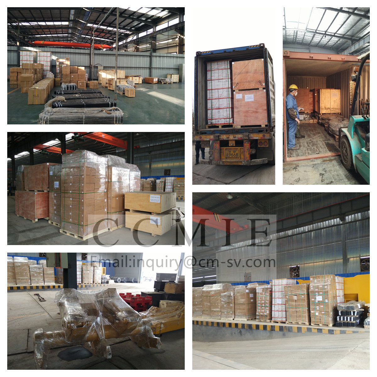
our warehouse

Pack and ship
- Aerial Boom Lift
- China Dump Truck
- Cold Recycler
- Cone Crusher Liner
- Container Side Lifter
- Dadi Bulldozer Part
- Forklift Sweeper Attachment
- Hbxg Bulldozer Parts
- Howo Engine Parts
- Hyundai Excavator Hydraulic Pump
- Komatsu Bulldozer Parts
- Komatsu Excavator Gear Shaft
- Komatsu Pc300-7 Excavator Hydraulic Pump
- Liugong Bulldozer Parts
- Sany Concrete Pump Spare Parts
- Sany Excavator Spare Parts
- Shacman Engine Parts
- Shantui Bulldozer Clutch Shaft
- Shantui Bulldozer Connecting Shaft Pin
- Shantui Bulldozer Control Flexible Shaft
- Shantui Bulldozer Flexible Shaft
- Shantui Bulldozer Lifting Cylinder Repair Kit
- Shantui Bulldozer Parts
- Shantui Bulldozer Reel Shaft
- Shantui Bulldozer Reverse Gear Shaft
- Shantui Bulldozer Spare Parts
- Shantui Bulldozer Winch Drive Shaft
- Shantui Dozer Bolt
- Shantui Dozer Front Idler
- Shantui Dozer Tilt Cylinder Repair Kit
- Shantui Sd16 Bevel Gear
- Shantui Sd16 Brake Lining
- Shantui Sd16 Door Assembly
- Shantui Sd16 O-Ring
- Shantui Sd16 Track Roller
- Shantui Sd22 Bearing Sleeve
- Shantui Sd22 Friction Disc
- Shantui Sd32 Track Roller
- Sinotruk Engine Parts
- Tow Truck
- Xcmg Bulldozer Parts
- Xcmg Bulldozer Spare Parts
- Xcmg Hydraulic Lock
- Xcmg Transmission
- Yuchai Engine Parts
Products categories
-
803191840 straight flange joint for XCMG GR300 ...
-

Q/CHL02.014-1999 Split flange AФ32.6/35 Changli...
-

318307831 BRACKET XCMG XE2000 HYDRAULIC EXCAVAT...
-
J901030 Bolt HITACHI EX2600E-6 Electric Excavat...
-

318307020 DIESELTANKHARNESS ASSEMBLY XCMG XE200...
-
208-27-71130 PC400-7 final drive sun gear excav...