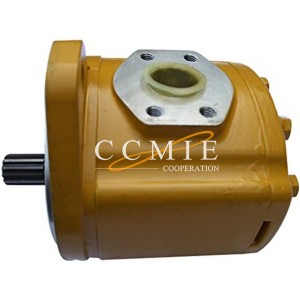
Steering knuckle XCMG Liugong motor grader spare parts


Steering knuckle
Because there are many kinds of spare parts, we can’t display them all on the website. Please feel free to contact us for specific ones.
Advantage
1. We supply both original and aftermarket products for you
2. From the manufacturer to the customer directly, saving your cost
3. Stable stock for normal parts
4. In Time Delivery Time, with competitive shipping cost
5. Professional and on time after service
Packing
Carton Boxes, or according to clients’ request.
description
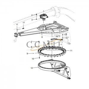
The steering knuckle is the hinge for the steering of the wheels, generally in the shape of a fork. The upper and lower forks have two coaxial holes for installing the king pin, and the steering knuckle journal is used to install the wheel. The two lugs of the pin hole on the steering knuckle are connected with the fist-shaped parts at both ends of the front axle through the king pin, so that the front wheel can deflect a certain angle around the king pin to turn the car. In order to reduce wear, a bronze bushing is pressed into the steering knuckle pin hole, and the bushing is lubricated by the grease nipple installed on the steering knuckle. In order to make the steering flexible, a bearing is installed between the lower ear of the steering knuckle and the fist-shaped part of the front axle. An adjustment pad is also installed between the upper ear of the steering knuckle and the fist-shaped part to adjust the gap therebetween.
Disassembly and assembly of steering knuckle
1. Disassembly
1. Remove the split pin, lock nut and spring washer.
2. Step on the brake pedal and loosen the hub nut. The hub and the drive shaft are connected together by the steering knuckle and fixed by the hub nut.
3. Lift and support the equipment, and then remove the front tire assembly.
4. Remove the hub nut and make sure that the drive shaft can be separated from the tooth groove of the hub when the steering knuckle is removed. Pull the drive shaft to separate the inner constant speed knuckle. If necessary, lightly hit with a brass punch.
5. Use a suitable removal tool to disengage the end of the tie rod from the steering arm.
6. Disassemble the brake hose retainer from the shock absorber.
7. Remove the clamping bolts that fasten the ball joint of the steering knuckle, and then tighten the brake caliper joint screws and washers.
8. Use a wire to hoist the brake caliper. Do not hang the brake caliper on the brake hose.
9. Remove the rotor, and then remove the ball joint stud from the steering knuckle assembly.
10. Remove the steering knuckle assembly from the grader. When disassembling the steering knuckle, support the drive shaft, and never allow the drive shaft to be suspended under the car after the steering knuckle is removed.
2. installation
1. Place the steering knuckle on the short post of the lower ball joint and pass the drive shaft through the hub.
2. Install the ball joint on the steering knuckle clamping bolt and tighten it to the specified torque.
3. Install the end of the tie rod into the steering arm, tighten the nut to the specified torque, and then install the split pin.
4. Install the rotor.
5. Install the brake caliper on the rotor and connect it to the steering knuckle. Install the brake caliper with connecting bolts and tighten to the specified torque.
6. Connect the brake hose positioner and shock absorber, and tighten the connecting screw to the specified torque.
7. Install the hub nut and pay attention to the following points:
(1) Step on the brake pedal, install the hub nut, and tighten it to the specified torque.
(2) Spring washers, lock nuts and new split pins are installed to make steering flexible. Bearings are installed between the lower lug of the steering knuckle and the fist-shaped part of the front axle. An adjustment pad is also installed between the upper ear of the steering knuckle and the fist-shaped part to adjust the gap therebetween.
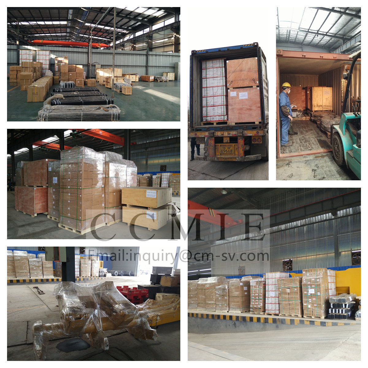
our warehouse

Pack and ship
- Aerial Boom Lift
- China Dump Truck
- Cold Recycler
- Cone Crusher Liner
- Container Side Lifter
- Dadi Bulldozer Part
- Forklift Sweeper Attachment
- Hbxg Bulldozer Parts
- Howo Engine Parts
- Hyundai Excavator Hydraulic Pump
- Komatsu Bulldozer Parts
- Komatsu Excavator Gear Shaft
- Komatsu Pc300-7 Excavator Hydraulic Pump
- Liugong Bulldozer Parts
- Sany Concrete Pump Spare Parts
- Sany Excavator Spare Parts
- Shacman Engine Parts
- Shantui Bulldozer Clutch Shaft
- Shantui Bulldozer Connecting Shaft Pin
- Shantui Bulldozer Control Flexible Shaft
- Shantui Bulldozer Flexible Shaft
- Shantui Bulldozer Lifting Cylinder Repair Kit
- Shantui Bulldozer Parts
- Shantui Bulldozer Reel Shaft
- Shantui Bulldozer Reverse Gear Shaft
- Shantui Bulldozer Spare Parts
- Shantui Bulldozer Winch Drive Shaft
- Shantui Dozer Bolt
- Shantui Dozer Front Idler
- Shantui Dozer Tilt Cylinder Repair Kit
- Shantui Sd16 Bevel Gear
- Shantui Sd16 Brake Lining
- Shantui Sd16 Door Assembly
- Shantui Sd16 O-Ring
- Shantui Sd16 Track Roller
- Shantui Sd22 Bearing Sleeve
- Shantui Sd22 Friction Disc
- Shantui Sd32 Track Roller
- Sinotruk Engine Parts
- Tow Truck
- Xcmg Bulldozer Parts
- Xcmg Bulldozer Spare Parts
- Xcmg Hydraulic Lock
- Xcmg Transmission
- Yuchai Engine Parts
Products categories
-
Komatsu grader variable speed pump 23A-60-11200...
-

803268688 piston rod for XCMG GR215A motor grad...
-
381200369 motor grader transmission system XCMG...
-
HD 9174ZZ XCMG cover mounting parts motor grader
-
380605114 worm gear box XCMG GR165 grader motor...
-
380401035 XCMG GR2605 cab assembly motor grader...